Acoustic Finite Element Models of Bass horns in Various Orientations in Rooms

Results of FEA work involving bass horns and various methods of orienting them in a room corner are shown. The primary goal was to investigate alternative methods of using the room corner and a space between the horn and the wall to extend the acoustic length of the horn. In addition, it was desired to investigate a lower than expected high frequency cut off observed with a 'real world' 27hz horn when oriented in a corner a certain way. All modeling was done in Matlab using the PDE toolbox. The plots below show some of the results of this work.

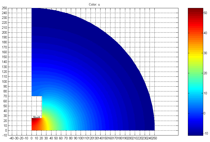
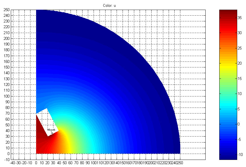
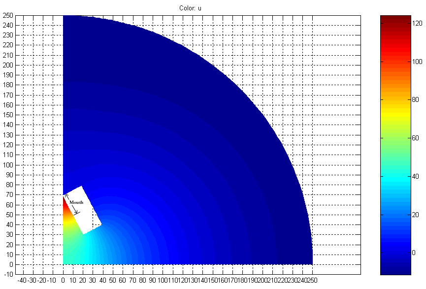
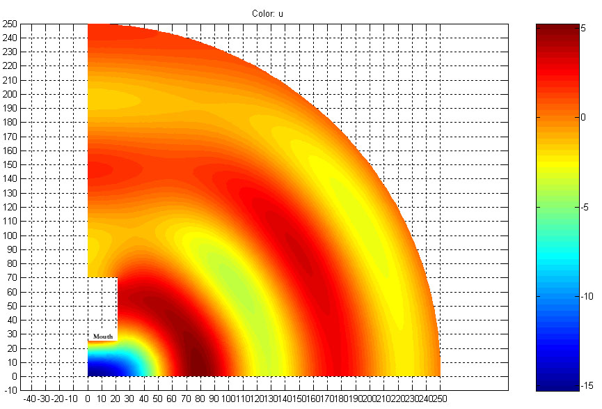
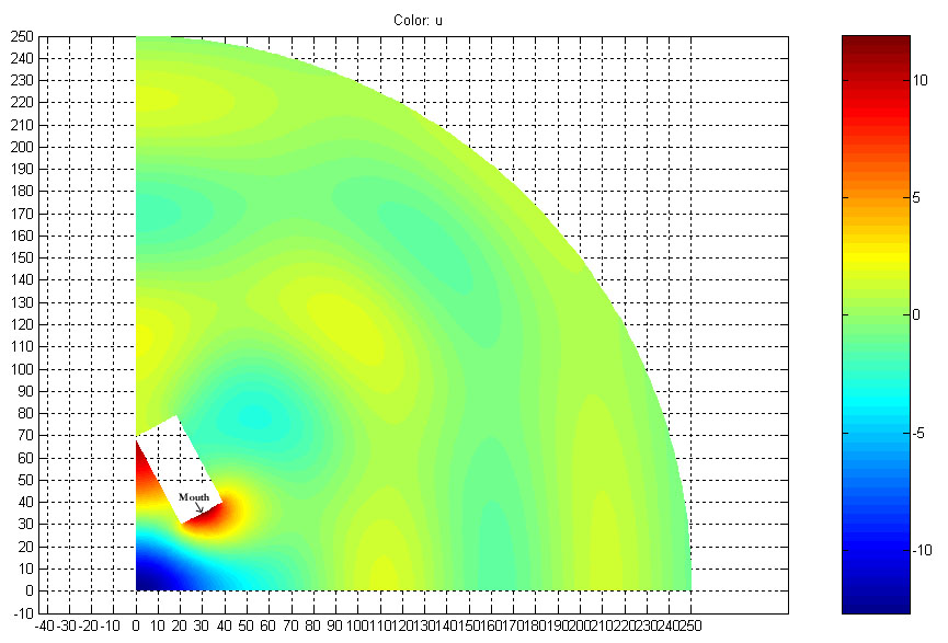
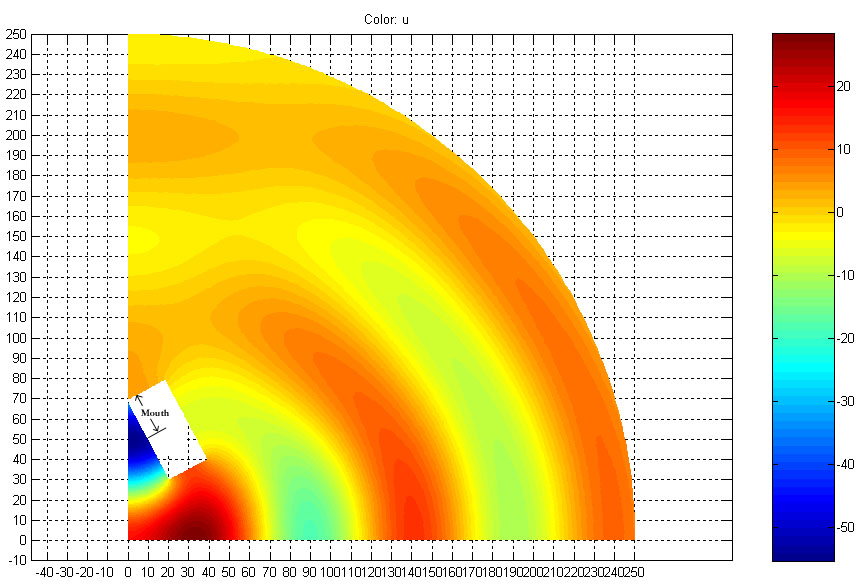
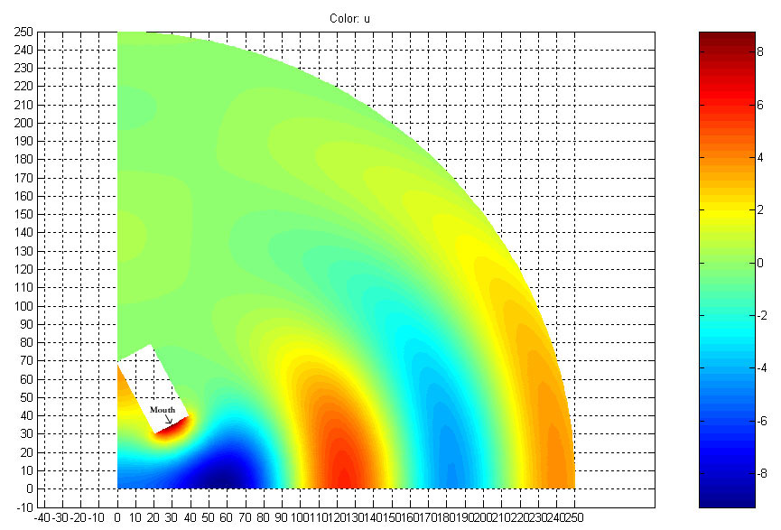
The quantity plotted is velocity potential. The first derivative of velocity potential with respect to time is equal to pressure times a constant. Because the velocity potential takes the form of a sine wave in time, it is representative of the pressure distribution.

The models shown are a horizontal cross section of the room through the horn. In each plot, the horn is the white rectangular box near the corner. It is about the size of a LAB horn (24" x 48") which is also the size of the 27hz horn that was measured. In each plot, the location of the mouth on the horn is indicated. The units on both axes are in inches (c is about 13538 in/s). Note that the color scales differ for each plot - see the legend on the right side of each for reference. Additional notes are given after each plot.


Low Frequency Comparison


Frequency of 20Hz with the horn mouth pointed into the corner.


Frequency of 20Hz with the horn angled out from the corner. This orientation should provide an acoustic extension of the horn at low frequencies. Real world measurements seem to verfiy that this is the case - the horn subwoofer described on this page plays to 40hz smoothly when pointed directly into the corner (first image), while it has a low frequency corner of 25hz when placed as shown above.


Frequency of 20Hz. This orientation puts the horn mouth at the rear of the 'wedge' of air between the room boundary and the horn wall. This orientation is used by the Sound Physics Labs 'B-DEAP subwoofer, and a patent is pending.


High Frequency Comparison


Frequency of 140Hz with the horn mouth pointed into the corner.


Frequency of 140Hz with the horn angled out from the corner.


Frequency of 140Hz for the 'B-DEAP' geometry.


Frequency of 120Hz with the horn angled out from the corner. This plot in conjunction with the 140hz plot above provides a possible explanation for the reduced high frequencies (above 100Hz) seen in the measured 27hz horn - note how half the space is not excited at 120hz. As measurements where taken at an angle of approximately 45 degrees from the room wall, this would have placed the microphone in a low pressure region for high frequencies.


Copyright 1999-2004, John H Sheerin

Click here to return to my home page.